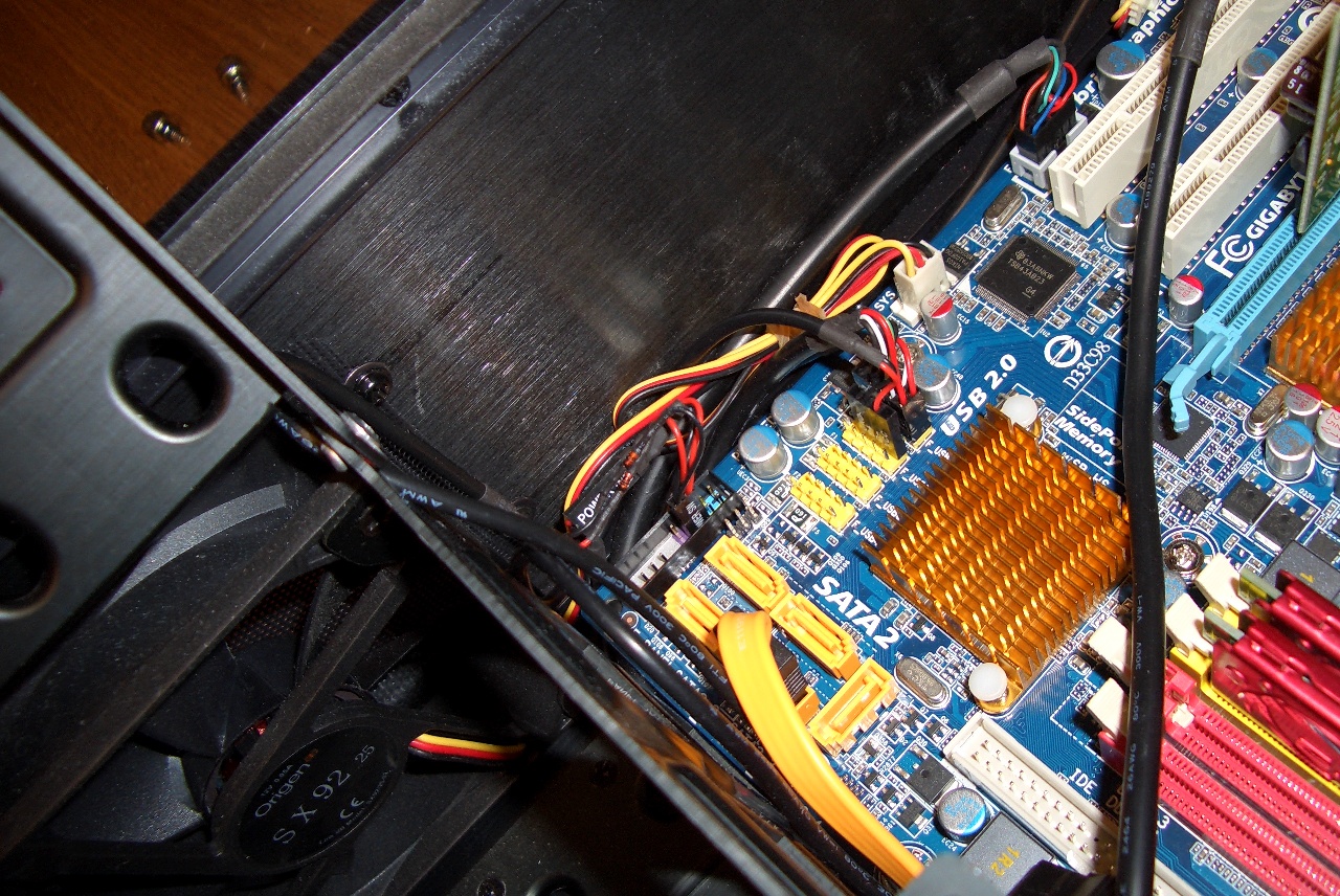
Remove Hard Drives.
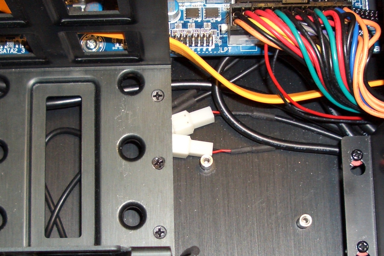
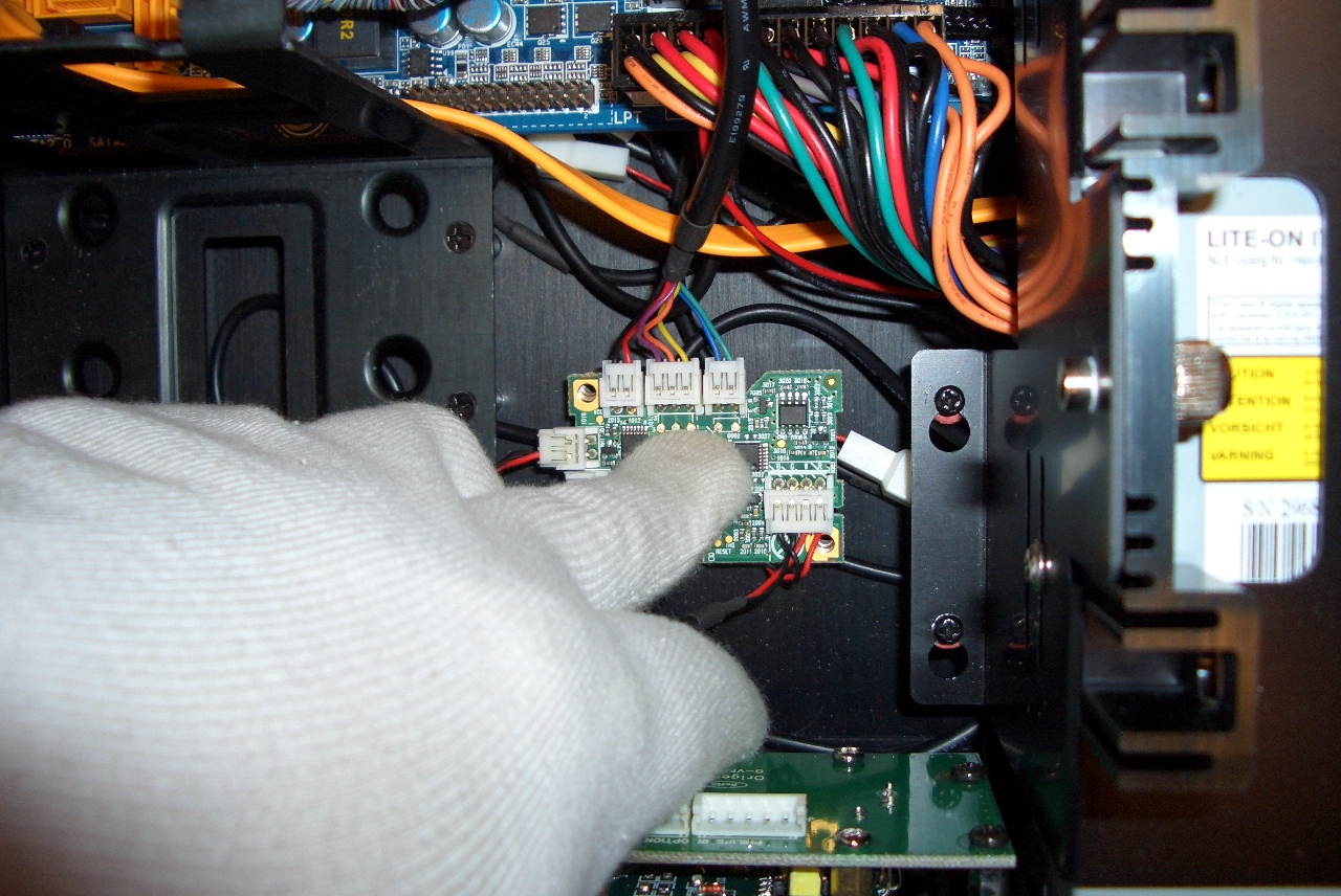
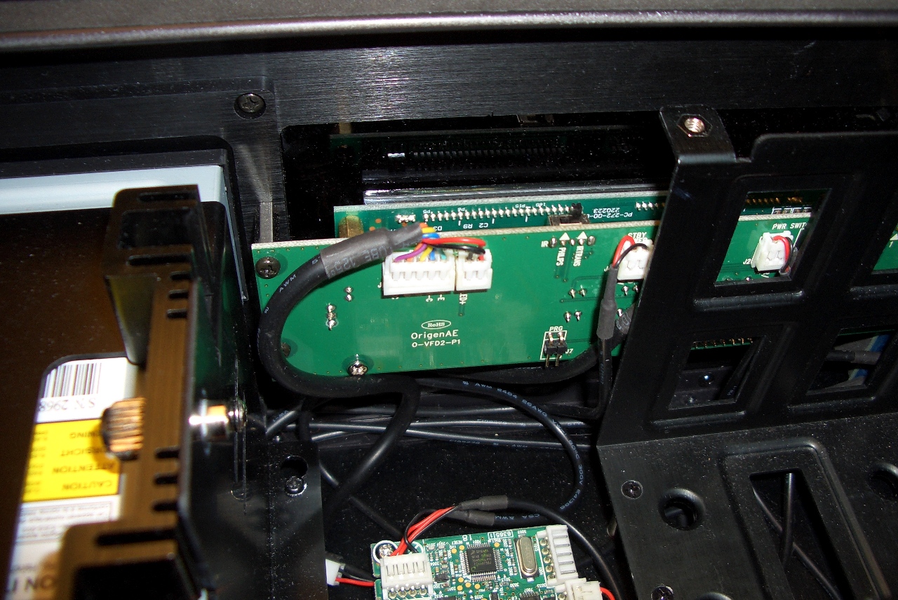
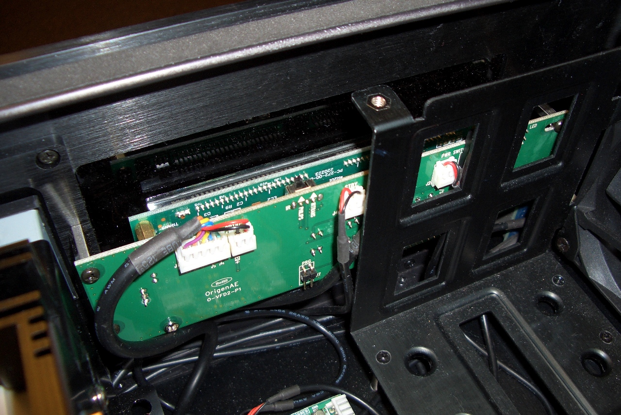
These two standoffs are for IR221 board. |
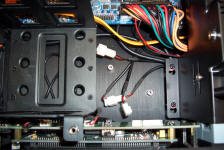
Disconnect one of Y splitter connectors. |
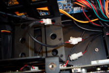
Attach supplied Y splitter and connect
to wire S-PUSB-C1 (# 7 on diagram) |
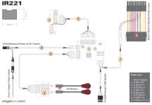
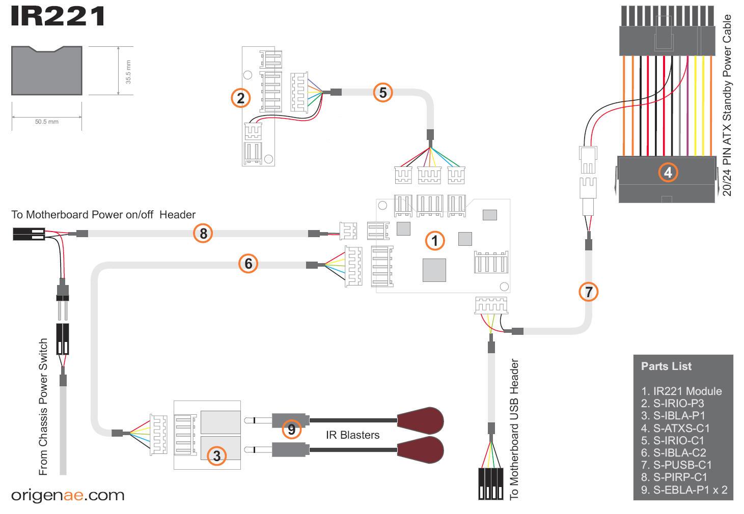
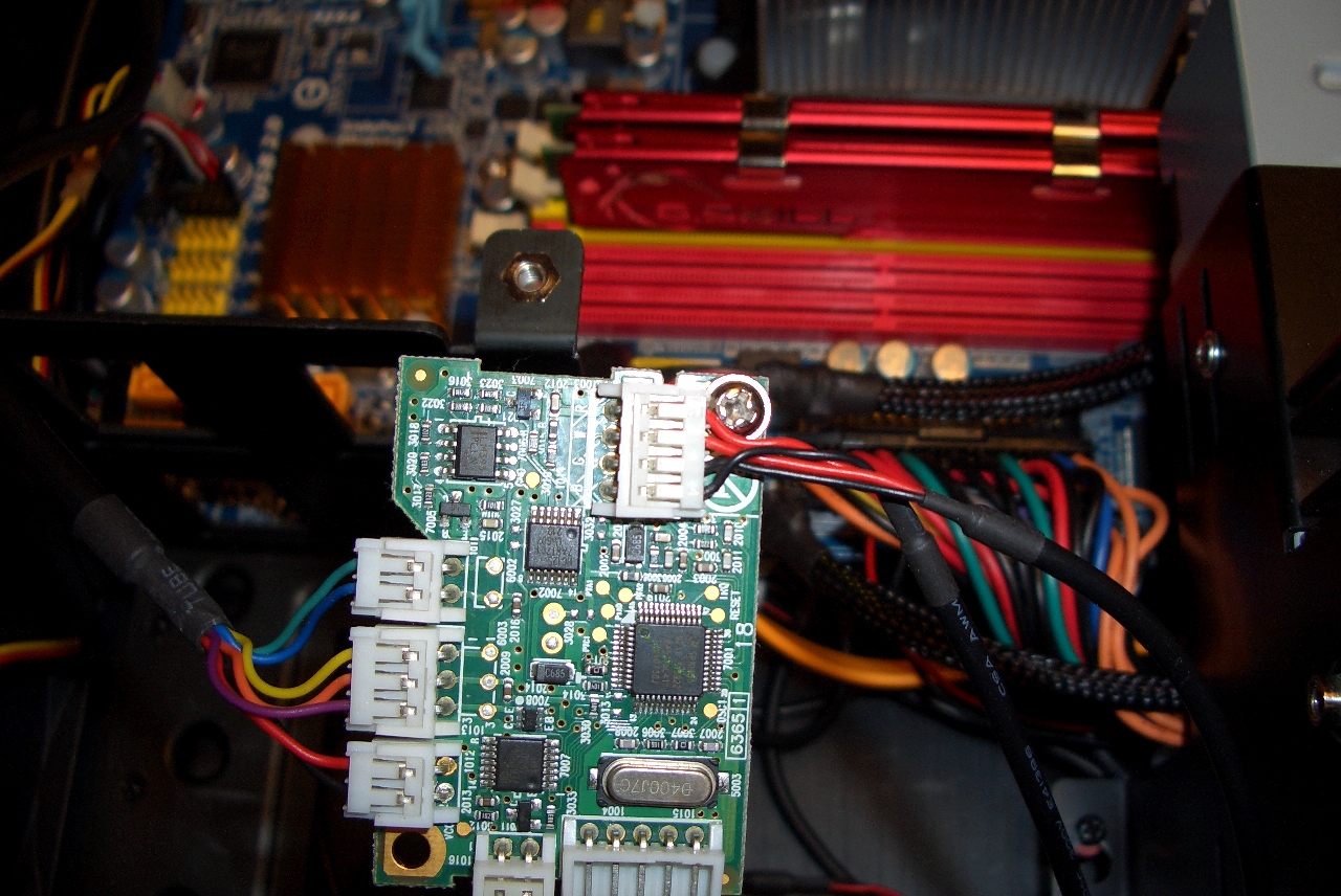
IR221 wiring diagram for S**T models. (there is
Y splitter supplied instead of #4 in IR221 small kit) |
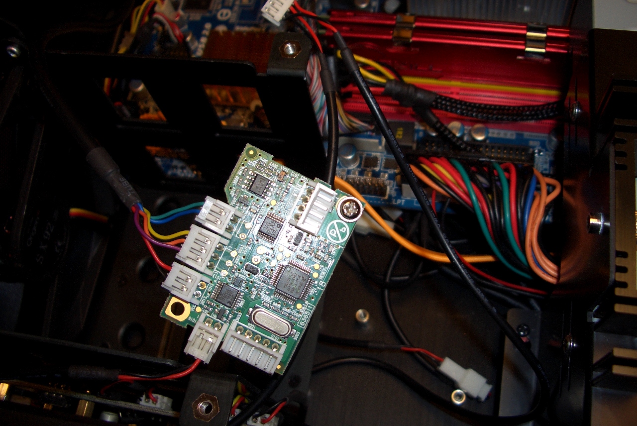
Connect USB connector to MoBo
|

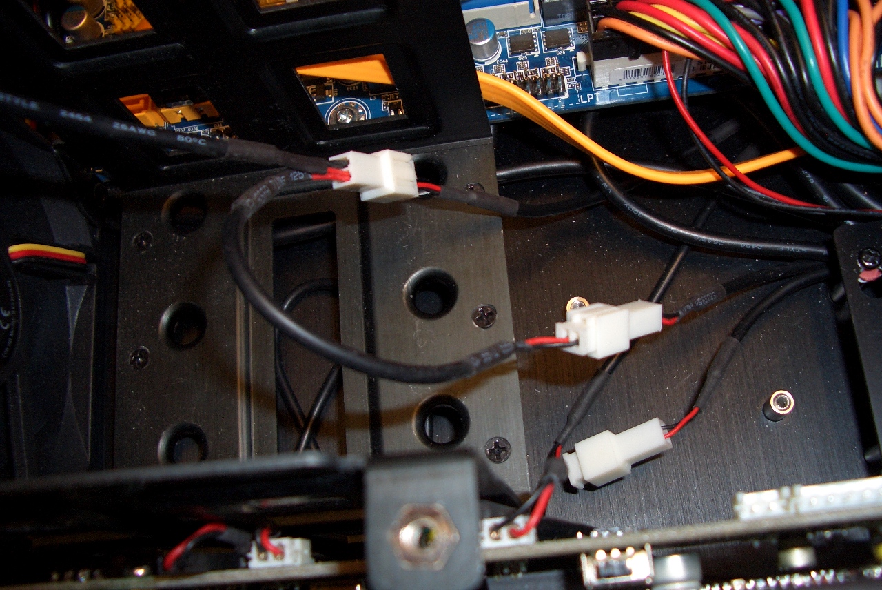
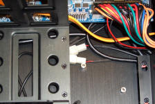
Disconnect power connector, install power splitter
(S-PIRP-C1 - #8) and reconnect it. |
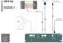
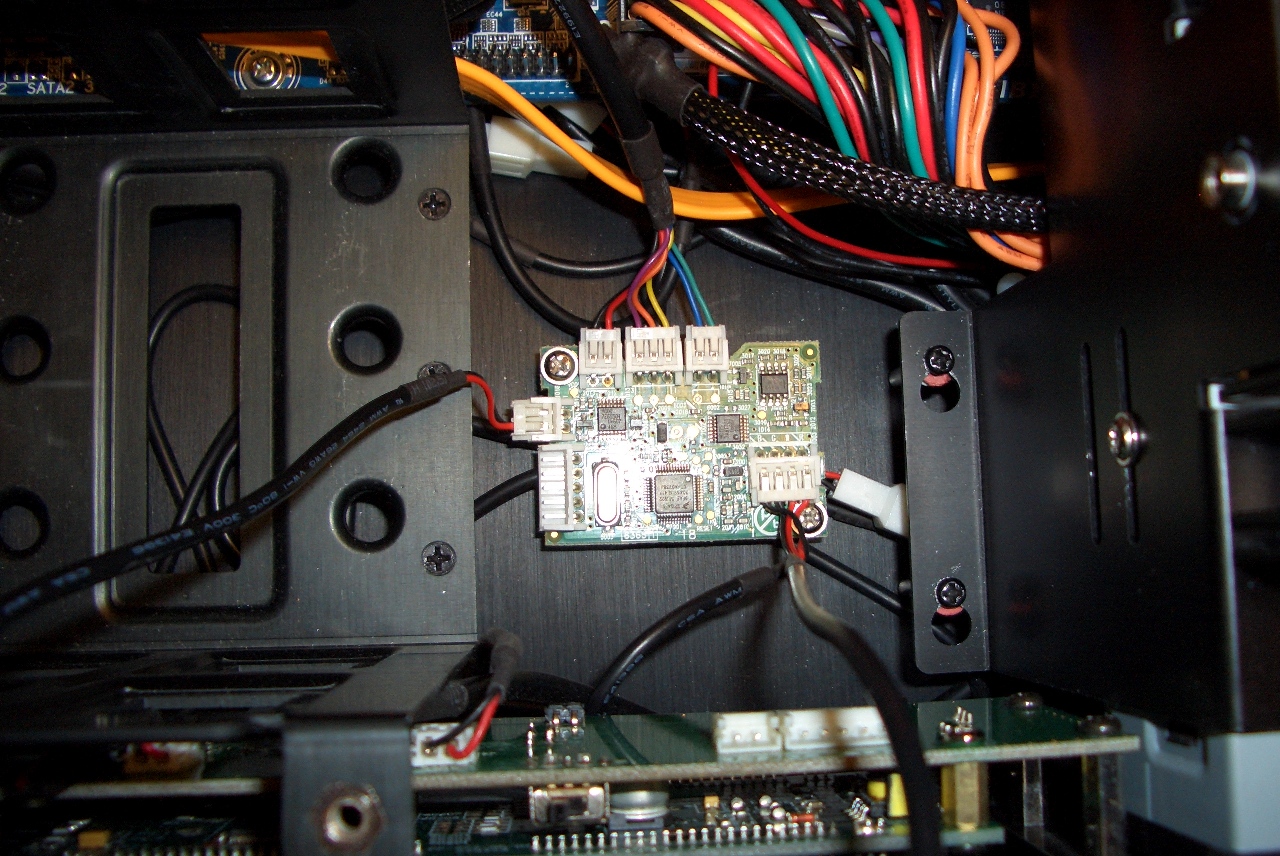
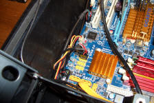
VF210 wiring diagram for S**V models |
When you add IR221 to
SxxV models, wire "5" must be connected to PHILIPS IR OPTION connector on
VF210, instead of IR receiver - board "2"
IR switch must be set to "Philips" position. |